


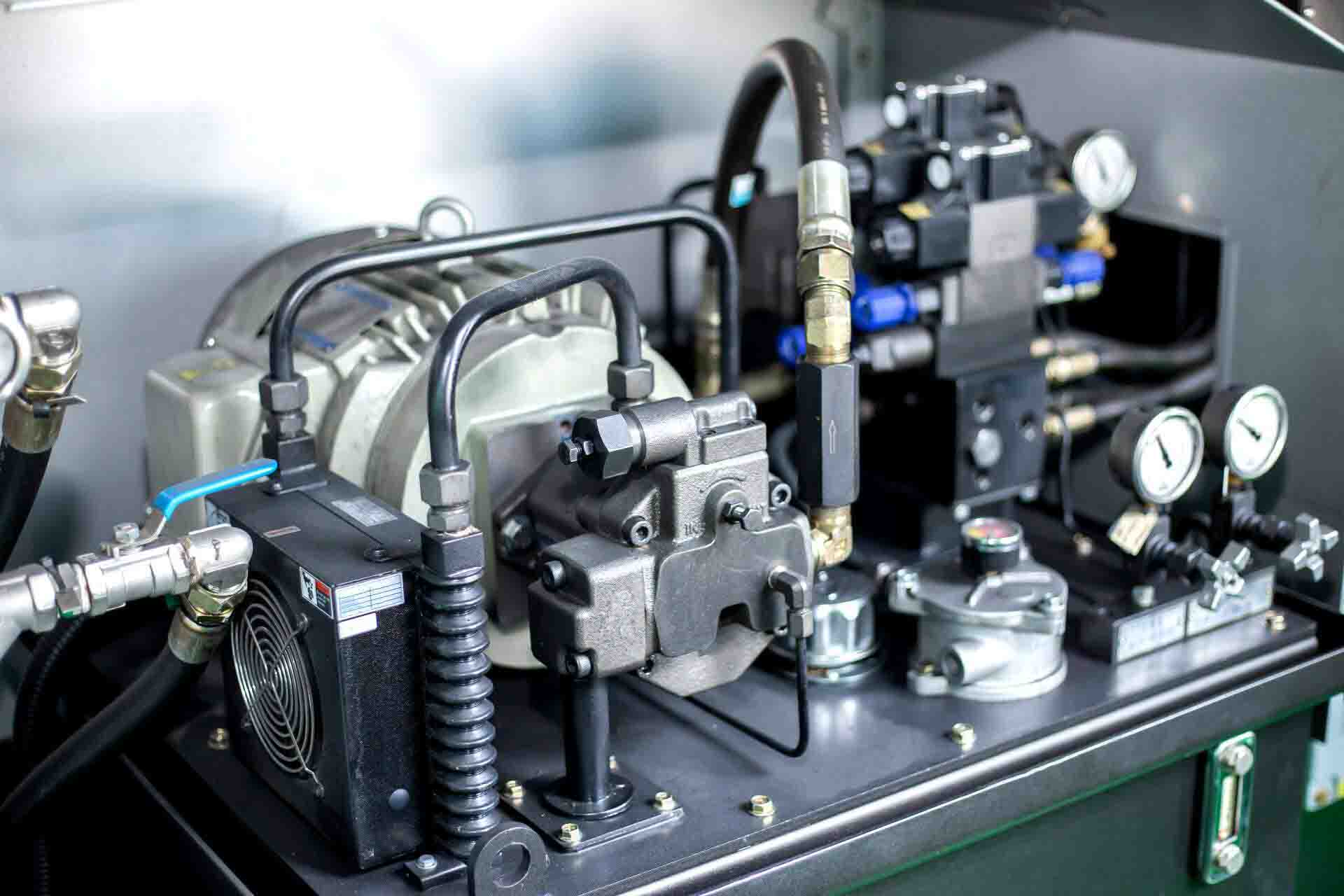
Successfully operating any type of hydraulic machinery is a matter of understanding the ins and outs of how it works. Operators must be aware of every detail of their equipment, from the precise amount of pressure it generates to the flow direction of the hydraulic fluid. This is difficult to do visually, however, because of the vast number of possible connections and interactions between various machinery types.
For this reason, system integrators like Aberdeen Dynamics provide detailed schematics to help workers understand the operating processes of each piece of hydraulic equipment. Specific, universal symbols are used in these schematics, and to successfully read them, operators must be able to interpret the symbols.
Following is a guide to the basic symbols used in hydraulic circuit diagrams. An understanding of these symbols will help trained employees learn to operate equipment more quickly and efficiently, so you can streamline your operation and avoid unnecessary delays.
Understanding Standards for Hydraulic Symbols
To ensure consistency across the entire industry, manufacturers rely on the symbols as they have been laid out by the International Standards Organization, or ISO. More specifically, the graphic symbols used in hydraulic systems are found in ISO 1219, which operators should familiarize themselves with.
In the United States, symbols for fluid systems are also standardized by the American National Standards Institute (ANSI). The specific symbols used in hydraulic machinery are found in ANSI Y32.10, which uses basic geometric shapes to demonstrate the purpose of each individual element in a system.
Besides the obvious benefit of creating consistency between otherwise dissimilar schematics, the system of symbols that these guides use also helps streamline the process of training operators. The simplicity of the symbols means that they can be interpreted easily: They are made up of basic geometric shapes, arrows, and other easily understood elements. As a result, users can quickly begin to understand the patterns behind them, meaning they can decipher even unfamiliar symbols without having to consult a chart each time.
Basic Symbols: Pumps
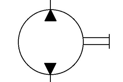
Symbol for a bidirectional pump
In both the ISO and the ANSI symbol guides, circles of various sizes indicate mechanical systems, including motors and pumps. Frequently, a circle with two parallel lines connected to it refers to a pump with a connection between the pump and a larger device.
Arrows are used to indicate the particulars of the pump’s operation, being used to denote the direction of fluid transfer. Two arrows inside the circle indicate it is bidirectional, while an additional arrow passing through the circle indicates a variable displacement system. Curved arrows may also appear on the schematic to indicate the direction of flow.
Valves
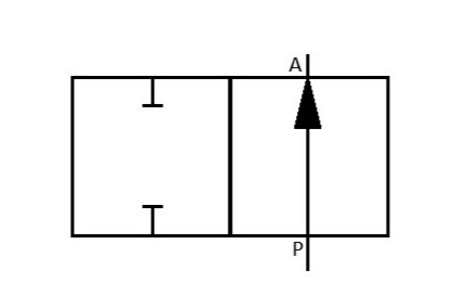
Symbol for a two-position valve
In ISO standardized hydraulic schematics, squares are used to indicate directional valves. Operators can determine the positioning of the valve by the number of squares used. A valve that has two positions (open and closed) will be indicated by two squares. One that has three positions (open, closed, and neutral) will be displayed on the schematic as three squares.
Other information that can be ascertained by the hydraulic symbols on the schematics includes the number and placement of the ports, which are usually labeled by letters like A, B, P, and T.
Other valves can be indicated by other symbols on the schematic. A zig-zag line means a spring in a check valve or pressure control valve, while cartridge valves are shown by a pentagon shape with ports on the top, bottom, and one side.
Cylinders
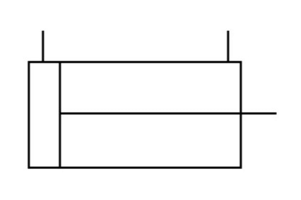
Symbol for a cylinder with a single-end rod
Understanding the cylinders in a hydraulic system is of major importance to the operators of any industrial equipment since they are the element that generates the motion in the machinery. How that motion is generated, in what direction it moves, and how much power can be created by a specific device can all be determined by the information on the schematic.
Cylinders are indicated on a schematic by a rectangle. One smaller rectangle inside the first rectangle indicates a single rod, while two means a double rod cylinder. Operators can determine if the cushions in the cylinder are adjustable by the presence of an arrow.
Fluid Lines
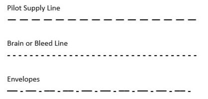
Fluid lines are another element of the system that greatly affects how it operates. Operators must be able to determine a large number of specifics based on the fluid transmission type. Simple working lines are displayed on the schematic as a straight line, while dashed lines refer to other types of flow lines.
Longer lines with short breaks in between them are depicted by a pilot supply line; however, if the lines are shorter with short breaks, then this means a brain or bleed line. Envelopes are indicated by dashes with dots in between them, helping operators determine the positioning of their valve spools.
For Further Information
The hydraulic symbols discussed above are the most basic of those that will be displayed on a hydraulic system schematic. All trained operators should understand them, but there are many more that can also be learned to help ease the processes of installation, maintenance, and production. Operators should always have easy access to the ISO and ANSI guides and refer to them as needed when consulting schematics.
A thorough understanding of hydraulic symbols will help your team members do their jobs more effectively, streamlining operations, keeping things running smoothly, and even increasing output. Aberdeen Dynamics designs and integrates high-end industrial equipment, and a large element of that is creating schematics that are easy for trained users to read and understand. Our custom hydraulic systems are designed by engineers and installed by expert technicians. We’ll help train your employees on the equipment and ensure they understand the schematics. Our team will help yours keep your equipment running so that you can achieve your maximum potential.